2. Working Voltage and Mode of Connection
2.1 Working Voltage: DC24V 36V 48V (set by the meter), other voltage could be customized.
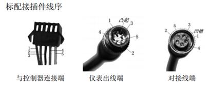
2.2 Mode of Connection:
Standard Connectors Line Sequence:
Red Line (D+): Power Positive
Black Line (GND): Power Negative
Blue Line (DS): Controller’s electric door lock
Brown Line (DD+): Lighting control’s Positive ( If the controller’s software and hardware support the lighting control, do not need connect this line)
Green Line (RX): Receiving communication
Yellow Line (TX): Sending communication
White Line (GND): Lighting control’s Negative
Extended Functions: PWM Assistance grades control, Independent external speed sensor
2. Functions
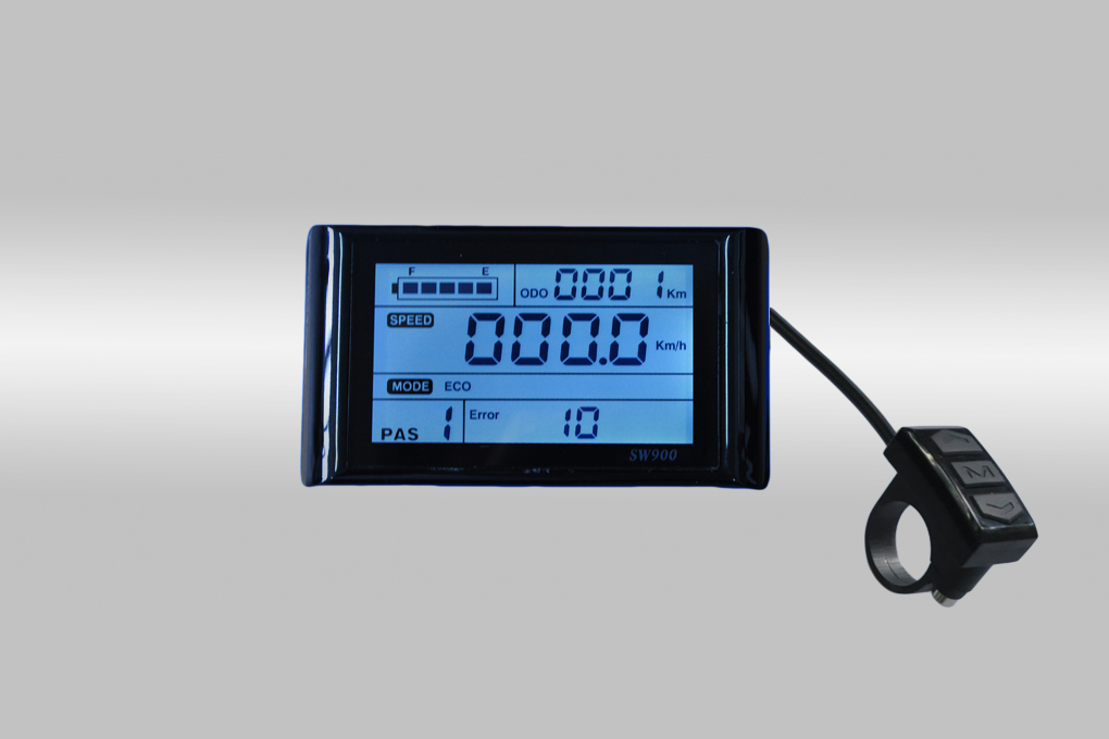
2.1 LCD Display
Speed indicator, PAS grades indicator, Battery indicator, Error indicator, Single Trip Distance and Total Distance, Headlight indicator.
2.2 Parameters Setting
Power on/off, Headlight on/off, 6KM/H Cruise control, Wheel size, Max speed setting, Auto stand-by and sleep mode setting, Background luminance setting, Working voltage setting.
2.3 Communication Protocol: UART
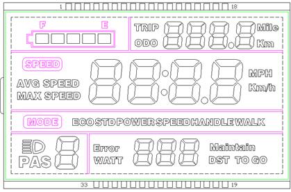
3. All contents on the screen
3.1 Headlight
3.2 Power status
3.3 Multi-functions
Total Distance(ODO), Single Trip Distance(TRIP), Error Code(Error), Wattage(WATT), Maintenance(Maintain), DST TO GO(Unused temporarily)
3.4 E-Bike Mode
Economic mode(ECO), Standard mode(STD), Powerful model(POWER), Hand speed-control model(SPEEDHANDLE), Walk assisted model(WALK)
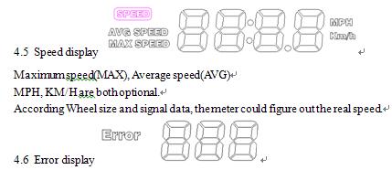
3.5 Speed display
Maximum speed(MAX), Average speed(AVG)
MPH, KM/H are both optional.
According Wheel size and signal data, the meter could figure out the real speed.
3.6 Error display
Meaning of Error Code:
|
Error Code |
Error Status |
Notes |
|
0 |
Normal Status |
|
|
1 |
Save |
|
|
2 |
Brakes |
|
|
3 |
PAS problem(a riding mark) |
not implemented |
|
4 |
6KM/H cruising |
|
|
5 |
Real-time cruising |
|
|
6 |
Battery is undervoltage |
|
|
7 |
Motor’s problem |
|
|
8 |
Throttle’s problem |
|
|
9 |
Controller’s problem |
|
|
10 |
Communication Receiving problem |
|
|
11 |
Communication Sending problem |
|
|
12 |
BMS Communication problem |
|
|
13 |
Headlight problem |
|
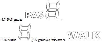
3.7 PAS grades
PAS Status (0-9 grades), Cruise mark
3.8 Parameters setting
P01 Background luminance. 1 is the darkest, 3 is the brightest
P02 Unit of the mileage. 0 is KM, 1 is MILE
P03 Voltage grades. 24V, 36V, 48V. The original voltage is 36V.
P04 Sleep time. 0 is without sleep, other numbers stand for the sleep time (1-60 min).
P05 PAS grades.
0, 3 grades mode: 1 grade 2V, 2 grade 3V, 3 grade 4V
1, 5 grades mode: 1 grade 2V, 2 grade 2.5V, 3 grade 3V, 4 grade 3.5V, 5 grade 4V
P06 Wheel size. Unit: inch. Precision: 0.1
P07 Speed measuring magnet. Range: 1-100
P08 Speed limit. Range: 0-50km/h, 50 means without limit
No-Communication Status (controlled by the meter): when the real speed is over the ones we set, the meter would shut off PWM output; when less than the speed we set, the meter would turn on PWM output automatically, the driving speed would be
±1km/h; (Speed limit is for PAS, not for Throttle)
Communication Status (controlled by the controller): The driving speed keeps same with the ones we set. Random error: ±1km/h. (Speed limit is for both PAS and Throttle)
Notes: These data are based on KM. When changing KM to Mile, the speed value on the screen would convert to correct Miles automatically, but if you do not change the setting of speed limit from KM to Mile, it would be different from the real speed limit in Mile.
P09 Zero start & Non-zero Start. 0 is Zero Start, 1 is Non-zero Start
P10 Driving mode.
0 is driven by PAS. Throttle is useless at this time.
1 is driven by Throttle. PAS is useless at this time.
2 is driven by PAS & Throttle. Throttle is useless at Zero Start status.
P11 PAS sensitivity. Range: 1-24
P12 PAS start strength. Range: 0-5
P13 PAS magnet type. There are 3 types: 5, 8, and 12.
P14 The Current-limiting of Controller. The original Current is 12A. Range:1-20A
P15 Not implemented now.
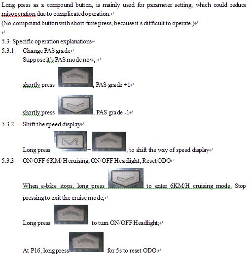
P16 Reset ODO. Long press for 5s, ODO could be reset.
4. Button Introductions